
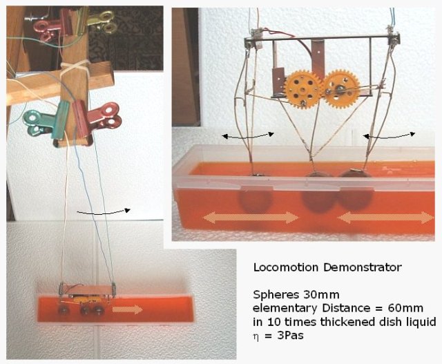
A Three Sphere Locomotion System
What is the simplest form of a system providing propulsion in viscous fluid? One of the rather simple systems is one of three spheres that are lined up on a straight line and which can change the distance to each other. The behaviour of this system will be investigated here.
Basic scale for the test set up
Starting from the practical side: What are suitable parameters for a model of the system? A basin of viscous fluid will have to have the width and the depth of at least two times the diameter of the sphere, and a sufficient length for the system to stretch out and to move.
If the spheres move for the distance of 2 diameters to each side, the stretched out length o the system is 7 diameters. Together with some way to move the length shall be 12 diameters.
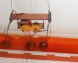
With 2 x 2 x 12 diameters the basin contains 48 cubic-diameters. Providing 1 litre of fluid for the experiment the size of a sphere could be 27.5mm or 30mm. The basin then has the size of 60 x 60 x 360 mm. A cutlery box of that size could be found for the test.
 |
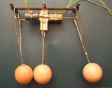
Three wooden spheres with 30mm diameter have a mass of about 30g and together with the construction and the motor the system has a mass of 90g. The weight of the system with the spheres in water ( buoyancy of 40cm³ ) is just 0.5N (50gf). A suitable propulsion could be in the range of 0.1N. A sphere moving with 0.1m/s will have to provide this force.
With the force F of a sphere moving in viscous liquid: F = 6 · π · r · η · v
η = F / (6 · π · r · v), this requires a viscosity of η = 3.5 Pas.
This is ten times the viscosity of dish washing liquid which is cheap but has just 0.3 Pas. The 10 times higher value of viscosity could be achieved, by evaporating 1/3 of the volume of the liquid.
The mechanical set up
The set up is made with the 3 spheres fixed to steel wires hanging into the basin. The wires are mounted to a drive system that swings out the spheres by 60mm to each side with a period of about 1 sec. The movement is according to a sinusoidal function with a phase difference of pi/2 between the spheres.
The system is hanging down as a pendulum with a length of 0.75m. This provides a guided mobility parallel to the centre of the basin. It also provides a force driving it back to the lowest point. This force is given by the weight, multiplied with the relation of the deflection to the length of the pendulum. For an effective weight of 0.5N, the force is 6.7mN per cm of deflection.
 |
 |
 |